Category: Uncategorized

  • Improving waste to energy plant performance

    Case Study 2

    Improving Waste to Energy Plant Performance by replacing frequently failing thermowells.

    Improving Waste to Energy Plant Performance by replacing frequently failing thermocouples

    Background

    OEM specified thermowells were failing every 1 to 2 months. Due to the location, the removal/replacement process was challenging, time consuming and expensive.

    Measuring task

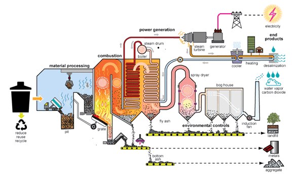
    Thermocouples were installed to monitor the very high temperatures in the ceiling and the second pass of the combustion chamber in order to monitor performance and the protection of the refractory as well as Sulphur and NOx which is a critical measurement for the emissions reporting.

    Customer issues

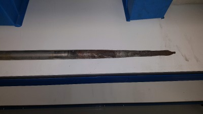
    The customer was experiencing high levels of thermowell failure due to corrosion caused by chlorides in the flue gas derived from burning of plastic (PVC). Inconel 800 had been selected for OEM design which was considered suitable to combat high temperatures (1000 Deg C) in the combustion zone. Chlorides were corroding the Inconel 800 thermowell within 1-2 months, resulting in failure and loss of signal.

    Due to the location, the removal/replacement process was challenging, time consuming and expensive. These measurements are critical to plant operation, frequent failures and swap outs are undesirable.

    Solution

    Special alloy material was used to manufacture the thermowells. This enabled them to withstand the high temperatures and also the corrosive effect of the variable flue gas chemical compositions.

    The result was increased reliability of temperature measurement. Inspection during the 6 monthly scheduled outage following the upgrade enabled an informed decision to confidently leave them installed until the next scheduled outage. The upgraded thermowells contributed to the safe operation of the combustion chamber refractory lining and control NOx released from the station, which is critical to fulfil emissions legislation.

    Improving Waste to Energy Plant Performance by replacing frequently failing thermowells.

    Click here to read Case Study 1

    Click here to return to Unplanned outages in waste to energy plants

  • Thermowells for corrosive environments

    Installing thermowells for corrosive environments can help you to eliminate failures between planned outages.

    Recently, one of our orders for bespoke thermowells was complete and Brian, Vanessa and Neale had an opportunity to further increase our understanding of how these items are vital within the Waste to Energy market.

    thermowells for corrosive environments
    thermowells for corrosive environments

    As well as being passionate about customer service we also like to improve our industry knowledge whenever possible.

    These 2m long thermowells were made for a W2E plant to solve a problem with the existing thermowells regularly failing between planned outages. The environment that these units operate in is particularly corrosive. The material that the OEM units were made from wasn’t up to the task.

    The customer provided us with a specification of the operating conditions; temperature and waste materials, in their boiler and a thermowell was designed to meet their demanding requirements. The material selected was a stocked exotic alloy. The cost of the alloy is more than other materials but not high when compared to the cost of unplanned outages due to failures.

    The adjustable, multipiece design makes it simple for the customer to swap out the old thermowells for the new ones with minimum fuss.

    Installing thermowells for corrosive environments can help you to eliminate failures between planned outages. At each planned outage, the thermowells can be inspected and assessed as to whether they need replacing at this time or whether they can be confidently left in place. The diameter of the thermowell can be measured to assess any deterioration due to corrosion or erosion. From the wear rate it’s possible to estimate the length in service and predict the optimum replacement cycle.

    Cost of ownership is only partly down to the cost of the equipment installed in the W2E plant. More significant costs are incurred from unplanned outages reducing plant availability and capability to incinerate waste and generate power.

    Posted: August 2022


    • Improving waste to energy plant performance

      Case Study 2 Improving Waste to Energy Plant Performance by replacing frequently failing thermowells. Background OEM specified thermowells were failing every 1 to 2 months. Due to the location, the removal/replacement process was challenging, time consuming and expensive. Measuring task Thermocouples were installed to monitor the very high temperatures in the ceiling and the second…

    • Cyber essentials certificate of assurance

      We’re delighted to announce that we’ve received the UK Government, Cyber Essentials Certificate of Assurance. This certifies that CHASE International Ltd was assessed as meeting the Cyber Essentials implementation profile and thus that, at the time of testing, the organisations ICT defences were assessed as satisfactory against commodity based cyber attacks. The assessment was not…

    • Thermowells for corrosive environments

      Installing thermowells for corrosive environments can help you to eliminate failures between planned outages. Recently, one of our orders for bespoke thermowells was complete and Brian, Vanessa and Neale had an opportunity to further increase our understanding of how these items are vital within the Waste to Energy market. As well as being passionate about…

    • Condenser tubes for power stations

      Condenser tubes for power stations are long, very long! And they take experience to manage the practical aspects of shipping and road transport. CHASE International is a leading supplier of condenser tubes for power stations. Together with our partners we have over 40 years experience in the supply of tubes produced from copper alloys, nickel…

    • Harsh conditions need specialist equipment

      Grinding applications in coal fired power stations and cement plants create harsh environments for equipment, including gear boxes. CHASE specialise in supplying gearboxes to the power generation and cement industries for crushing applications. All the gear systems and parts that we supply are proven to withstand harsh grinding conditions and are engineered to exact customer…

    • We’ve never built a complete power station

      Posted: June 2022 We’ve never built a complete power station but… we’ve supplied just about every spare part possible to stations in over 100 countries. We supply spare parts for: Coal handling• Vertical pulverizers• Coal handling motors• Low friction linings Boiler (coal, gas or waste)• Stop valves• Control vales• Globe valves• Parallel slide gate valves•…

  • Unplanned outages in waste to energy plants

    Unplanned outages in waste to energy plants

    Unplanned outages in waste to energy plants are a serious problem resulting in reduced throughput, loss of income or even fines. In addition to cost, unplanned outages cause significant issues with out of hours call outs, disrupted work schedules and unbudgeted costs.

    Unplanned outages can happen for all sorts of reasons; one common cause is when all the temperature sensors in the incinerator are damaged in quick succession due to the thermowells, that are there to protect the sensors, failing.

    Shutdowns can cause damage to plant, meaning that components will need replacing before the system can be restarted, or increase wear on components leading to reduced life expectancy. Damage to plant and increased wear on components increases the number of weak points in the system and increases the likelihood of shutdown in the future.

    In some facilities in the Waste To Energy industry the plant is built to a budget that doesn’t allow for consumables of a high enough specification to enable smooth running, especially within the warranty period. Once the plant is beyond the warranty period (ie post- warranty) it would allow for an upgrade to higher spec thermowells.

    Thermowells may be regarded as a low-cost consumable on the original plant budget but can increase risk of plant downtime later. The cost difference comparing OEM-supplied thermowells and those specified to effectively protect the temperature instrumentation effectively is insignificant compared to the costs of shutdowns and unplanned outages.

    The common causes of thermowells failing are mechanical, corrosion, erosion and vibration fatigue. Thermowells can be manufactured in a range of specialist materials and profiles in order to cope with the demanding and unpredictable environments in incinerators.

    bkw damaged thermowell waste to energy
    bkw damaged thermowell tip waste to energy

    Reduction in unplanned outages in waste to energy plants

    We have two case studies available, outlining Waste to Energy plants that have upgraded their thermowells and enjoyed significant improvements in life expectancy and plant availability.

    Click on the links below to read:

    Case Study 1

    Case Study 2

    Use the contact form below to get in touch. Please give us some basic information about the temperature of your incinerator and the general nature of the waste being processed and we will provide a recommendation and cost for thermowells that would be suitable for your plant.

  • Replacing frequently failing thermowells

    Case Study 1

    Improving Waste to Energy Plant Performance by replacing frequently failing thermowells.

    Improving Waste to Energy Plant Performance by replacing frequently failing thermocouples

    Background

    OEM specified ceramic high temperature thermocouples were failing every few weeks.

    Measuring task

    The thermocouples were installed to measure temperatures of 1000 C to 1600 C in the 1st and 2nd pass phases inside the combustion chamber to monitor burn performance and control Nox, a critical measurement for emissions. Configuration is a set of 3 pieces in a 2oo3 voting system (SIL Loop).

    Customer issues

    The customer was experiencing frequent failures of the ceramic thermowell on start up and shutdown due to ‘thermal shock’.

    Additionally in the 2nd pass, thermowells were suffering abrasion due to fly-ash within the stream, reducing the lifespan of the thermocouples to a few weeks.

    Solution

    Both of the issues experienced by the customer were addressed by installing appropriately specified thermowells to protect the thermocouples whilst allowing them to function effectively.

    For thermal shock the thermowells had a special ceramic sheath material to handle very high temperatures and the heat/cool cycle experienced.
    For the 2nd pass, an alternative alloy material material was offered for the thermowell pocket due to HCI (byproduct of burning plastics/polymers) and Urea (dosed into the stream to control NOx levels). The presence of fly ash causes abrasion and reduces thermowell life which was addressed by offering a very hardwearing coating on the sheath.

    Improving Waste to Energy Plant Performance by replacing frequently failing thermowells.

    The effect of the new thermowells was to extend the life of the thermocouples from 8-10 weeks to beyond 12 months.

    Click here to read Case Study 2

    Click here to return to Unplanned outages in waste to energy plants

  • Stop Check Valve

    In many applications the use of a combination of a stop valve and a check valve is used.

    This results in two pressure containing parts, two potential leak paths and the added issues of space and especially weight.

    Based on globe valves, stop-check valves have been developed in the past. By mounting a loose disk on the spindle, the disk can function as a check valve. The main disadvantage is that these valves in most cases have not been designed as stop check valves. A second disadvantage is the fact that the pressure drop over this type of valves is high, due to the change in flow direction.

    If we build the start stop combination, based on two different pressure-containing bodies, the unit would be identical to this drawing.

    stop check valve

    There are two pressure seal bonnets and two heavy forged valve bodies, welded together or welded in different sections of the line. In total we have to deal with three or four welds, although AVS can carry out the welds between the check valve and the gate valve in the factory.

    Other disadvantages are the space requirements, the additional weight, the extra insulation needed and also the additional cost factor.

    Furthermore, the maintenance and inspection costs for these combinations, have to be based on two valves.

    Latest Developments

    New developments within Persta have combined the tapered parallel slide gate valve, with a full swing check valve, brought together in one valve body.

    Based on a standard gate valve body and standard stock items a stop-check valve can be created.

    With a swing check valve and the straight through pattern of the valve body the pressure drop is negligable. When the valve is required to be closed an additional disk is lowered on a second downstream seat.

    The mounting arrangement of the second disk is provides a positive closing force on the swing check disk resulting in a tight bidirectional closure. Now the stop-check valve is performing as a tapered parallel slide gate valve.

    Based on standard Persta hollow forgings, high pressure equipment can be built. It is evident that the costs of a combined stop-check valve are much lower than the conventional use of a separate stop valve and check valve. Especially where pressures and temperatures are high, the features of the new Persta stop-check valve provide many advantages.

    Applications for Stop Check Valves

    In industry there are many possible applications.

    In many power stations where there are two gas turbines, two HRSG’s and one steam turbine, a check valve and a stop valve are installed in the main steam lines. Depending on pressure, temperature and capacity a 12”, 16” or 20” valve combination brings a better performance and a more economic approach. Our gate-check valves are available in different materials, such as ASTM A 182 F12, A 182 F 22, and A 182 F 91.

    Every high pressure pump is fitted with a check valve. If this check valve can be combined with a stop valve in the same line, a significant saving can be achieved. High pressure forged check valves and gate valves provide weight and subsequently cost savings.

    Our gate-check valves are available in different materials, such as the EN equivalent of ASTM A 182 F1 and DIN /EN WB 36 (1.6368). (ASTM A 533 Gr B, C and D).

    In the oil and gas industry, produced water is re-injected into the well. These pumps do have a check valve and a stop valve. Combining it into the Persta stop-check valves gives a considerable saving in space and weight. Please check the availability of materials, such as Duplex, Super Duplex and 254 SMO.

    Copyright © Advanced Valve Solutions 2012

  • Improve efficiency increase profits

    There is a high probability that you can generate more profit from your power station

    CHASE International would like to help you to examine the issues surrounding critical valve applications in CCGT power plants, in
    particular plants with Alstom GT 24 and GT 26 turbines.

    We look at the causes of common issues and then discuss innovative, proven solutions.

    What we would like to do for your installation and how:

    • We would like to help you to improve the total efficiency of your installation and to reduce maintenance and operational costs.
    • We would like to help you to go through your system and
      review your design and current parameters, operational hours and hardware.
    • Based on the information gathered we will be able to provide you with proposals for improvements.

    The annual financial benefits can vary from relatively small to substantial. However, even smaller benefits can make a substantial contribution to your profitability, especially when keeping in mind that these benefits will be there year after year.

    To give you an idea of the annual benefits that can be obtained we have listed a few examples below. These are based on a power station with a capacity of about 900MW.

    DESUPERHEATERS (SYSTEM)

    Potential Annual Benefit: $80,000 to $110,000. Payback in approximately four months.

    Cooled High Cycle Desuperheater

    MAIN STEAM STOP AND CHECK VALVES

    Potential Annual Benefit: $120,000 to $150,000. Payback in approximately eight months.

    main steam stop valve

    SUPERHEATER DRAIN SYSTEM

    Potential Annual Benefit: $80,000 to $100,000. Payback in approximately three months.

    superheater drain system

    ONCE THROUGH COOLER

    Potential Annual Benefit: $5000 per start. Payback in approximately three months.

    once through cooler
  • Once through cooler valves for gt24/26 turbines

    OEM OTC Valve

    Significantly Reduce Start Up Times

    Save £1000’s Per Start In Short Term Marginal Costs

    So over a period of 4 years, what I expect based on the data we received from an installation where we have installed the specially designed OTC valve, we can save approx. GBP 102,000 = (parts only)

    Download OTC Valve Flyer

    What is a once through cooler

    once through cooler

    The Majority of gas turbines require cooling of the main power turbine blades and vanes. To cool the turbine blades, compressed air is tapped off from the compressor part of the gas turbine, the compressed air is then cooled in a Once Through Cooler (OTC).

    The OTC is a heat exchanger, with hot air on the shell side and water/ steam as refrigerant on the tube side.

    The feed water, which is taken from the economizer of the HRSG, flows through the OTC and cools down the hot (compressed) air. It is evaporated and superheated when leaving the cooler. This steam is fed back into the HRSG superheater.

    The cooled air is used to cool down the blades of the turbine (film cooling) and to heat up the combustion chamber. As the cooling of the turbine blades is crucial for the gas turbine it is of the highest importance that the outlet
    temperature of the air coming out of the OTC is controlled within a margin of only a few degrees.

    Common problems with oem supplied otc valves

    • Seat / trim wear
    • Poor position control at low flow
    • Speed of response

    Original supplied OTC valves are often valves with a staggered disc trim. This trim construction is based on a staggered pile of disks, all individually having channels (see picture) with a multi-stage pressure reduction, controlled by a plug moving up and down within the disk stack. Stroking of the plug is opening or closing individual discs giving more or less flow.

    The solution—design a specific valve

    A multi-stage cascade valve, 5+1 up to 7+1 stage pressure reduction (depending on max differential pressure (dp) with 3 mm dead stroke and flow direction on the plug. This first part of the stroke gives the valve the time to overcome hysteresis and to “activate” all the stages in the trim before the real control function begins.

    The cascade trim is a proven design multi-stage pressure reduction, capable of continuously reducing an increasing or decreasing mass flow. With flow on the plug and Kv values per stage matching the flow demand, cavitation cannot occur and flashing is removed from the seat area to the outlet of the trim where wear is not affecting the function and leakage class of the trim. The plug design makes this trim less sensitive to magnetite and particles compared with a staggered disc trim.

    OTC Valve Trim

    Features

    • 5 to 7 controlled pressure reduction stages
    • Full control over total stroke
    • No seat hammering
    • No cavitation
    • Flashing away from the seat area
    • Less sensitive to magnetite
    • No stepping

    Advantages

    • Stable start-up
    • Reduction in start-up time (filling the OTC / flame on phase)
    • Strong reduction in GT trips during start up (longer maintenance interval GT)

    Cost benefits

    Cost savings are based on reduced time to start the GT (ignition phase). In current installations we have seen an improvement of about 15 to 20 minutes.

    • Phase one: get the water level right in the OTC
    • Phase two: constant air outlet temperature to the GT combustion chamber and first GT vane rows
    • Phase three: transition to PID controller

    Saving 15 to 20 minutes in start up time is a direct saving on gas and is a quicker delivery of energy/power to the grid.

    Let’s say an installation with one GT and one HRSG, total capacity 450 MW (typical for a GT26 installation)

    15 minutes is: 0.25 x 450 = 112.5 MWh

    In the UK the rate which is used for the Capacity Auction Market is around GBP 20 / MWh. However in case power is required by the grid, rates can vary between GBP 50 to 900 per MWh.

    Based  on GBP 20/MWh an installation can make 112.5 x 20 = GBP 2,250 more with each start  (quicker on the grid)

    Based on GBP 50 /MWh an installation can make 112.5 x 50=  GBP 5,625 more with each start.

    Maintenance

    Instead of replacing an expensive trim every year (some installation each half year) we have an maintenance interval of at least 3 years and most likely much longer.

    Typical cost for a staggered disc trim from the GT26 OEM is GBP 30,000

    Typical cost for a complete spare set for an OTC valve is GBP 18,000

    So over a period of 4 years, what I expect based on the data we received from an installation where we have installed the specially designed OTC valve, we can save approx. GBP 102,000 = (parts only)

    Download OTC Valve Flyer

  • Valve Innovation and Optimisation Workshop May 2017

    Al Dur Power Plant

    CHASE International are delighted to announce The Valve Innovation and Optimisation Workshop, held at Engie’s Al Dur CCGT Power Plant in Bahrain, on 7th/8th and repeated on 9th/10th of May 2017.

    The Valve Innovation and Optimisation Workshop is a two-day series of presentations and seminars, in conjunction with our partners Advanced Valve Solutions. The speakers include independent industry experts and experienced engineers from European valve manufacturers, Hora and Persta. It is designed for people who require an understanding of the impact that changes in operation can have on operation costs, plant availability, valve reliability, controllability, maintenance intervals and life time expectancy.

    The workshops are aimed at enlightenment and are not simply a ‘sell’ of products etc, rather an understanding of fundamental and innovative designs solutions to known problems within the process industries.

    Valve Innovation and Optimisation Workshop

    I am interested in receiving more information about the workshop.

    [contact-form-7 id=”1117″ title=”Contact IO Workshop”]

    Changes in power station operational demands, in recent years, have produced significant impact on plant operational costs, with an emphasis on valve reliability and overall station efficiency, maintenance and valve controllability. We discuss in detail how we can offer an alternative view on advancements in preferred materials and innovation in valve design all being impacted on by dual shift and stop/start requirements.

    The workshop provides a unique insight into the commonly occurring problems with dual shifting (stop/start) power plants. These include the impact on both isolation and control valves.

    Many design, project and maintenance engineers have benefitted from Valve Innovation and Optimisation Workshops by applying the knowledge gained and understanding preventative measures that can be applied to reduce plant down time, operational costs and increase station efficiency.

    Programme

    Day 1: Control Valves, HORA

    Registration
    Welcome, program explanation
    HORA, control valves, function and applications

    Lunch

    Transfer
    Workshop 1: Calculation of valves, design
    Workshop 2: Materials, QA / QC
    Workshop 3: Bypass stations, HP, IP, TAL
    Workshop 4: (Cooled) attemporators
    (Attendees can choose three workshops)

    Day 2: On-off valves, PERSTA

    PERSTA, on-off valves, function and applications
    Which valve is located where

    Lunch

    Transfer
    Workshop 1: DRA
    Workshop 2: EN / ANSI / ASME, design to P and T
    Workshop 3: Actuators
    Workshop 4: Maintenance
    Workshop 5: Materials, forging, casting, welding, P91, F22
    (Attendees can choose three workshops)

    The program included opportunities to discuss specific topics and asks questions.

    This educational event is offered free of charge to engineers working in the power industry. Participants are responsible for their own travel arrangements and costs.

    If you would like more information about this event, please complete the form, send us an email to source@chaseint.co.uk or call our UK Head Office on +44 (0) 1925 755221.